

Today’s networks have security and visibility requirements that can warrant complicated designs. A proper routing design takes time. Implementing security takes some thought. Having a properly segmented network goes beyond tossing a bunch of VLANs on a switch. One of the goals in a segmentation design is to engage the business and find out the who, what, where and why of communication in the network. If you know those business purposes, you can design around it. You can implement routing and firewall rules to control who or what has access to certain assets. In this entry to the blog, I have implemented a basic segmented network using EVE-NG. Let’s take a tour!

Above is the topology for the single lab site that I have weaved segmentation into. We have mostly Cisco infrastructure with the firewall being a Palo Alto VM on version 10.0. The TinyCore Linux box is what I used to configure the Palo Alto. The Chicago-WAN01 router is simply used to aggregate the site’s networks into BGP and advertise into the “MPLS”. The MPLS is just another router. The action happens on our Chicago-CORE01 layer 3 switch. There we have several VLANs for different purposes.

Depending on the environment, you can have many more VLANs to manage. For this simple example, I created a few for our “office” environment. We know how those troublemakers in payroll want to snoop around the network. I’m pretty sure HR is also up to some dastardly scheme too! The goal here is that utilizing the firewall we have visibility to where our site’s traffic is attempting to go. Perhaps it is traffic that we need to allow. The IT team will most likely need some sort of remote access to other subnets. However, HR probably does not need to remote in to machines in Payroll. Those are all the things you need to find out when you begin designing segmentation. At its most basic, here we have VLANs separating out different office functions. The VLAN’s are tied to Switch Virtual Interfaces (SVIs) on the Chicago-CORE01 layer 3 switch.
Chicago-CORE01#sh run | sec Vlan
 interface Vlan2
  description Admin MGMT
  ip address 10.0.0.2 255.255.255.0

 interface Vlan10
  description Office_HR
  ip vrf forwarding Office_HR
  ip address 10.0.1.1 255.255.255.0

 interface Vlan11
  description Office_Payroll
  ip vrf forwarding Office_Payroll
  ip address 10.0.2.1 255.255.255.0

 interface Vlan12
  description Office_IT
  ip vrf forwarding Office_IT
  ip address 10.0.3.1 255.255.255.0

 interface Vlan13
  description Voice
  ip address 10.0.4.1 255.255.255.0

 interface Vlan14
  description Office_Wireless
  ip vrf forwarding Office_Wireless
  ip address 10.0.5.1 255.255.255.0

 interface Vlan15
  description Guests
  ip vrf forwarding Guests
  ip address 10.0.6.1 255.255.255.0
If you did not notice, some of the networks above were placed into Virtual Routing and Forwarding (VRF) instances. This separates that network completely with it’s own routing table. My goal is that each network is not aware of other networks on the Core switch. One thing to look out for is the max number of VRFs you can create on a particular device. In order for these networks sitting in a VRF to communicate, they would need to route through the firewall and then if permitted, the firewall would allow those networks to communicate to the destination. You probably noticed I did not place the Admin and Voice networks behind the firewall. The Admin network is device management. In order for other subnets to reach out to the admin network, they would still need to cross the firewall. Voice is one we can probably go back and forth on. Some engineers do not want the voice environment behind a firewall so there are no possible issues with the voice traffic. Others are fine with it. With enough bandwidth and proper rules we should be fine, but I’ll let everyone argue this one out. For this example, the voice network is sitting in the Global Routing Table (GRT). Routing-wise, each VRF has a default route to the Palo Alto firewall. In order for IT to communicate with HR, the default route would take them to the firewall.
Chicago-CORE01#show run | inc ip route
 ip route vrf Guests 0.0.0.0 0.0.0.0 10.0.6.2
 ip route vrf Office_HR 0.0.0.0 0.0.0.0 10.0.1.2
 ip route vrf Office_IT 0.0.0.0 0.0.0.0 10.0.3.2
 ip route vrf Office_Payroll 0.0.0.0 0.0.0.0 10.0.2.2
 ip route vrf Office_Wireless 0.0.0.0 0.0.0.0 10.0.5.2
As you can see in the snippet above, each VRF has a default route pointing over to the next-hop which resides on the firewall.
Let’s talk about routing and how we communicate with the firewall from the Core switch. Between the Chicago-CORE01 and the Palo Alto firewall, we have a point to point connection.
interface Ethernet0/3
  description Uplink: PA1/1 Internal
  no switchport
  ip address 10.0.250.1 255.255.255.252
This /30 is what allows us to setup OSPF routing between the core switch and firewall. If we take a look at our GRT, we will see the other OSPF routes from the Palo Alto.
Codes: L - local, C - connected, S - static, R - RIP, M - mobile, B - BGP
D - EIGRP, EX - EIGRP external, O - OSPF, IA - OSPF inter area
N1 - OSPF NSSA external type 1, N2 - OSPF NSSA external type 2
E1 - OSPF external type 1, E2 - OSPF external type 2
i - IS-IS, su - IS-IS summary, L1 - IS-IS level-1, L2 - IS-IS level-2
ia - IS-IS inter area, * - candidate default, U - per-user static route
o - ODR, P - periodic downloaded static route, H - NHRP, l - LISP
+ - replicated route, % - next hop override
Gateway of last resort is 10.0.250.2 to network 0.0.0.0
O*E2 0.0.0.0/0 [10/1] via 10.0.250.2, 1d23h, Ethernet0/3
10.0.0.0/8 is variably subnetted, 13 subnets, 3 masks
C 10.0.0.0/24 is directly connected, Vlan2
L 10.0.0.2/32 is directly connected, Vlan2
O 10.0.1.0/24 [110/20] via 10.0.250.2, 2d00h, Ethernet0/3
O 10.0.2.0/24 [110/20] via 10.0.250.2, 2d00h, Ethernet0/3
O 10.0.3.0/24 [110/20] via 10.0.250.2, 2d00h, Ethernet0/3
C 10.0.4.0/24 is directly connected, Vlan13
L 10.0.4.1/32 is directly connected, Vlan13
O 10.0.5.0/24 [110/20] via 10.0.250.2, 2d00h, Ethernet0/3
O 10.0.6.0/24 [110/20] via 10.0.250.2, 2d00h, Ethernet0/3
C 10.0.250.0/30 is directly connected, Ethernet0/3
L 10.0.250.1/32 is directly connected, Ethernet0/3
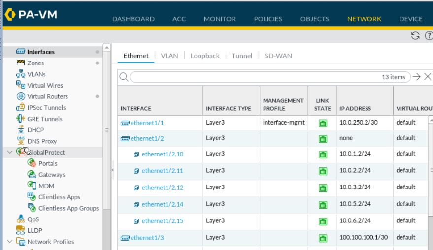
O E2 10.10.1.0/24 [110/1] via 10.0.0.1, 1d23h, Vlan2So what happens on the firewall? In production on a physical firewall, I would aggregate several interfaces together. In this example only ethernet1/1 from the Chicago-CORE01 is a trunk to ethernet1/2 on the firewall. The Palo Alto VM does not support aggregated interfaces. In production, we would want to see what our firewall throughput is (along with other features) and based on that, aggregate interfaces together to fit the size of the traffic we are pushing over to the firewall. Once the interfaces are aggregated, you would create sub-interfaces for each of the networks. Each network resides in its own zone. This also means you want to look at the number of zones supported by your device.
Let’s take a look at the zones.
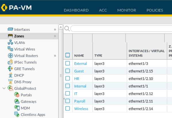
We have put together the pathways that our “cars” will travel down, but here is where we discuss the tollbooths. The firewall rules I tossed into this example are pretty simple rules. We are allowing most of the zones back in through the Internal zone towards the MPLS. We are also allowing zones out to the internet (the External Zone). IT has access to all zones. Guests only have access out to the internet.

Well, production should not look that simple. Here is the part that will take the longest amount of time. As the engineer, you will need to engage the various owners of servers, services, and end points to see what they need access to. What services does server A need to allow from HR or IT? A lot of what comes back will be “Um….I actually don’t know.” In the beginning when implementing segmentation, rule sets will probably have to be Any to Any rules from different zones. However, that should not be the end game. Putting together objects, groups, and rules will take time, but in the end it will be worth it. This also means requests will be a bit more controlled and hopefully organized into a Change Management procedure or at least a simple firewall rule request form.
We took a look at basic segmentation in my EVE-NG lab. Implementing something like this in production will take some efforts. Always plan ahead. Making sure you are aware of your device’s capabilities will be key. The conversations you have with different teams that own those end points using your network is needed in order to create a rule set that makes sense. In the end, we want to move a step closer to a zero trust network. Let’s start laying the foundation!

Leave a comment